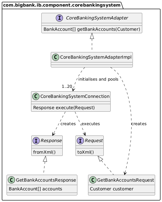
Code diagram
Finally, you can zoom in to a component to show how it is implemented as code; using UML class diagrams, entity relationship diagrams or similar.
This is very much an optional level of detail and is often available on-demand from tooling such as IDEs. Ideally this diagram would be automatically generated using tooling (e.g. an IDE or UML modelling tool), and you should consider showing only those attributes and methods that allow you to tell the story that you want to tell. This level of detail is not recommended for anything but the most important or complex components.
Example
Scope
A single component.
Primary elements
Code elements (e.g. classes, interfaces, objects, functions, database tables, etc) within the component in scope.
Intended audience
Software architects and developers.
Recommended?
No, particularly for long-lived documentation because most IDEs can generate this level of detail on demand.