Microservices
Broadly speaking, there are two options for diagramming microservices when using the C4 model, although it depends what you mean by “microservice”. With that in mind, let’s start from the beginning.
Stage 1 - monolithic architectural style
Imagine that we work for a small startup company and our task is to build a software system (named “X”) that offers business capabilities A, B, and C to our customers. Our system context diagram might look like this:

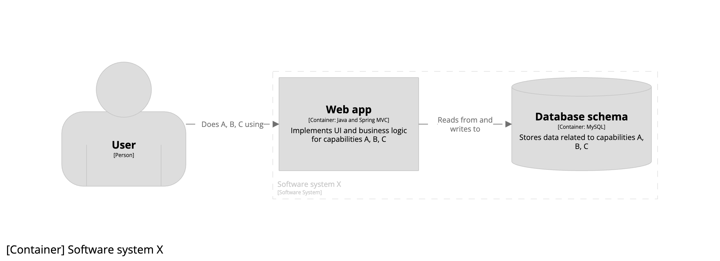
Arguably the quickest and cheapest way to get something delivered, especially as a young startup with a small engineering team, is to use a monolithic architecture, consisting of a single monolithic web application reading from and writing to a single monolithic database schema. The resulting container diagram looks like this:
Stage 2 - microservices architectural style
A couple of years have gone by - we have some paying customers, traffic is starting to scale, we’ve hired a few more engineers, and the codebase is growing. Our monolithic architecture is starting to slow us down, so we make the decision to transition to a microservices architecture. That raises the question - what is a microservice?
To answer this question, we’ll refer to Microservices written by James Lewis and Martin Fowler:
In short, the microservice architectural style is an approach to developing a single application as a suite of small services, each running in its own process and communicating with lightweight mechanisms, often an HTTP resource API. These services are built around business capabilities and independently deployable by fully automated deployment machinery.
To help us align this with the C4 model, let’s substitute “application” for “software system”:
In short, the microservice architectural style is an approach to developing a single software system as a suite of small services, each running in its own process and communicating with lightweight mechanisms, often an HTTP resource API. These services are built around business capabilities and independently deployable by fully automated deployment machinery.
In this stage of our startup’s journey, although we’ve hired a few more engineers, we’ve decided to stay as a single engineering team. Our system context diagram remains the same:

But our container diagram has changed. We’ve decided to retain the single monolithic UI of the existing web application, but move the business logic and data into individual microservices. The resulting container diagram now looks like this:
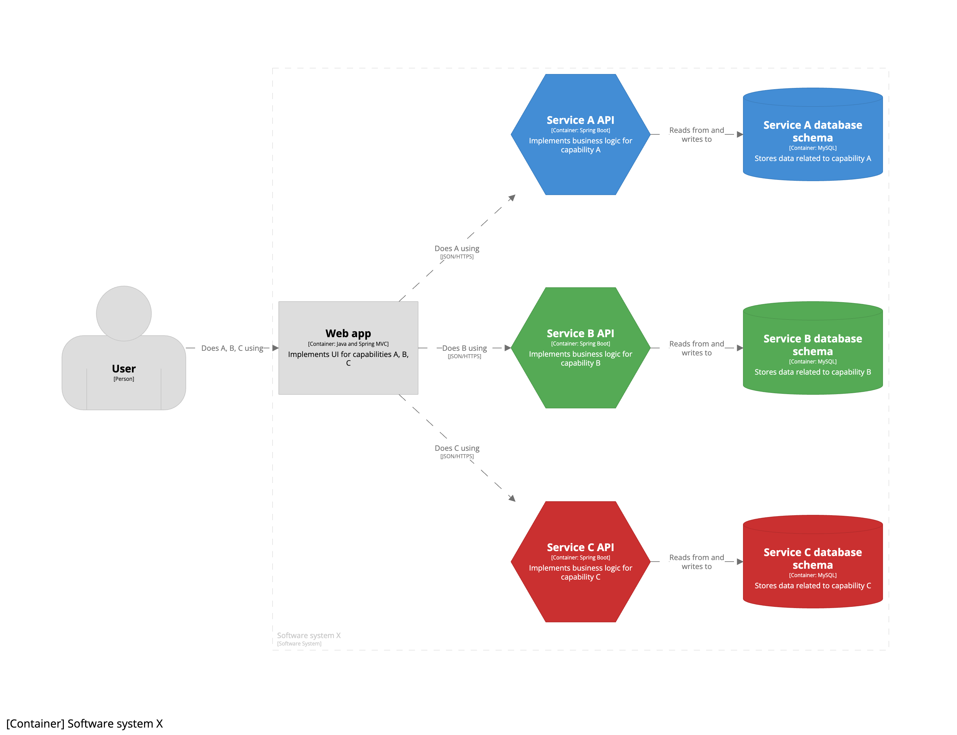
As we’re still a single engineering team, transitioning to a microservices architecture is an implementation detail that is only apparent inside the team boundary. This is why all seven containers are shown inside the software system boundary, with each “microservice” being a combination of an API container (hexagon) and a database schema container (cylinder). As a result, you will notice that this container diagram doesn’t show microservices as explicit boxes. Instead, this version of the diagram uses colour coding to show the relationship between pairs of API and database schema containers. If you wanted to be more explicit about this pairing, you could draw a box around each pair to show they are grouped together.

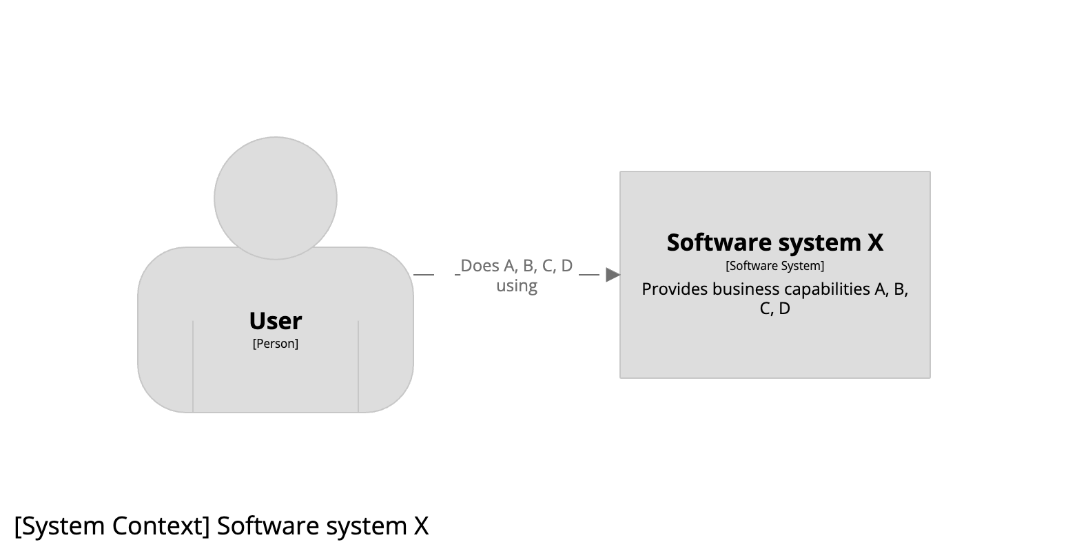
Imagine now that we are going to expand the scope of our software system to also include business capability D. The revised system context diagram would look like this:
And if that new business capability was implemented by a new microservice, which is just a single stateless AWS lambda, the revised container diagram would look like this:
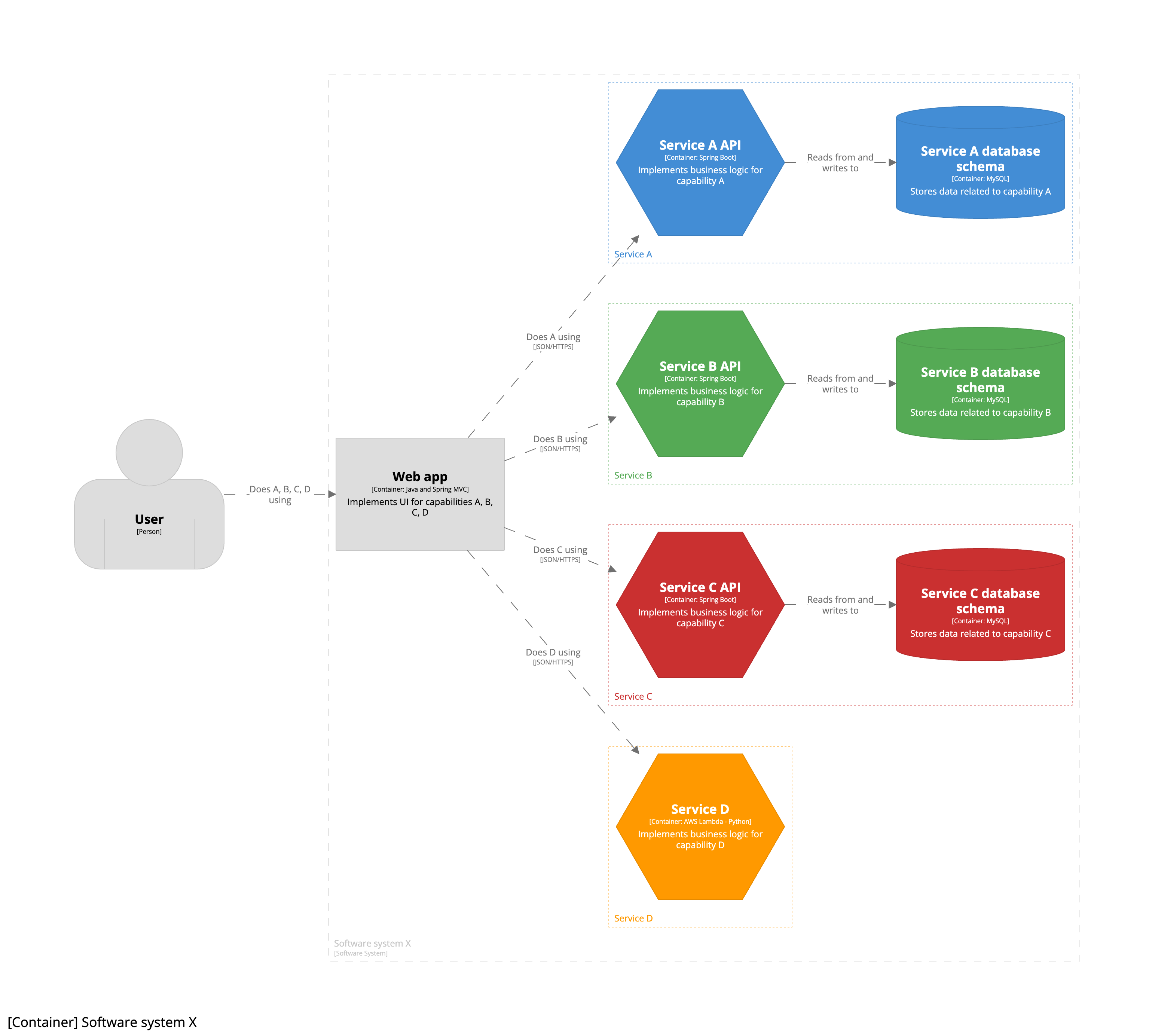
To summarise, all the microservices shown here exist within the context of a single team building a single software system. For this reason, each microservice is modelled as a group of one or more containers.
Stage 3 - Conway’s Law
As our company grows, and moves from startup to scaleup, we start looking at ways to optimise delivery, and decide to look at Conway’s Law as a way to do this. In summary, we decide to split our single engineering team into a number of teams, the result of which is that each service will be owned by a separate team:
- Team X: owns software system X providing the UI related to business capabilities A, B, C, and D.
- Team A: owns service A.
- Team B: owns service B.
- Team C: owns service C.
- Team D: owns service D.
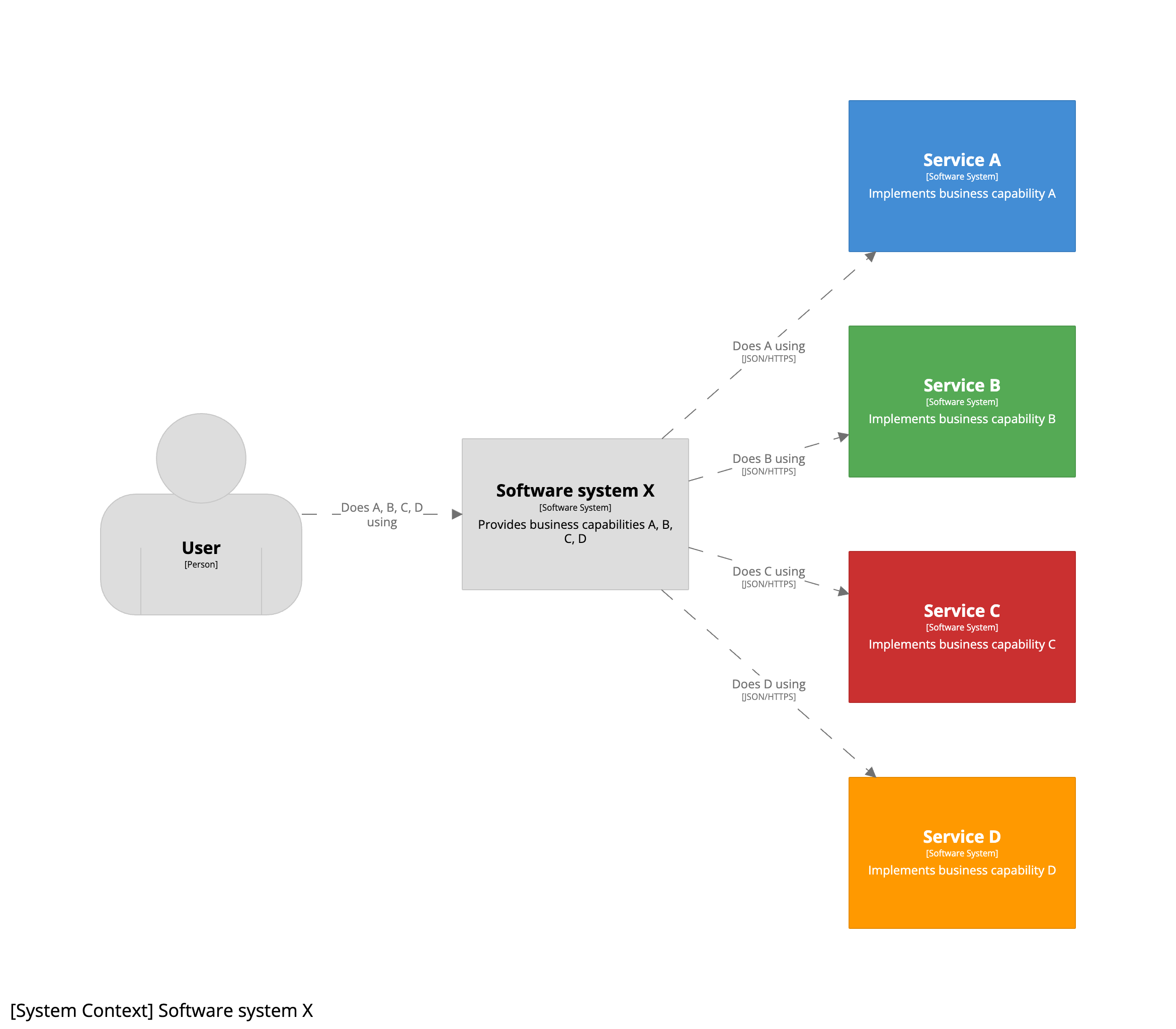
We can now use the C4 model to look at each software system from the perspective of the team that owns it, with each service being “promoted” from a group of containers to a software system. The system context diagram for team X now looks like this:
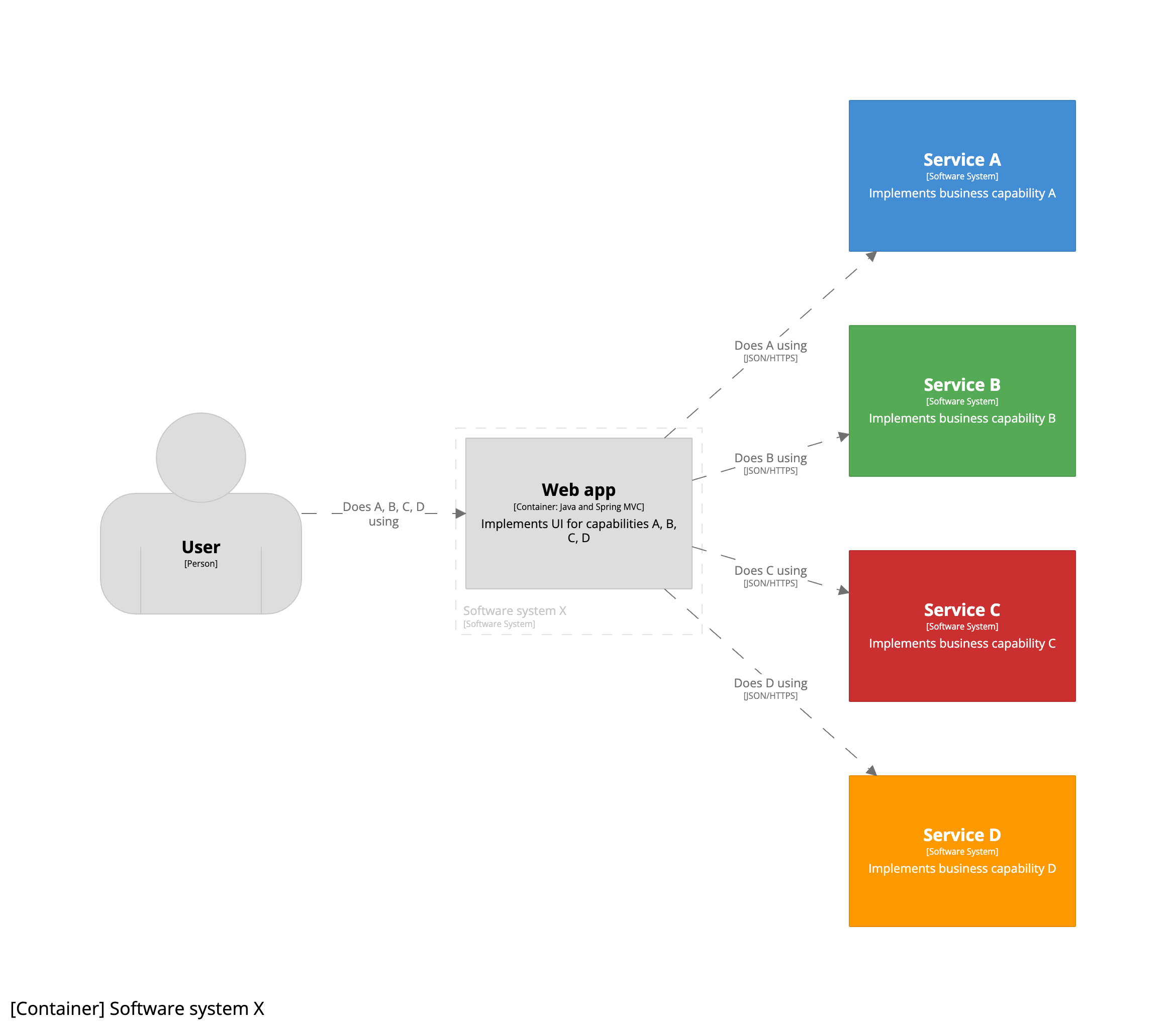
Team X has only retained the monolithic UI, so the revised container diagram for software system X looks like this:
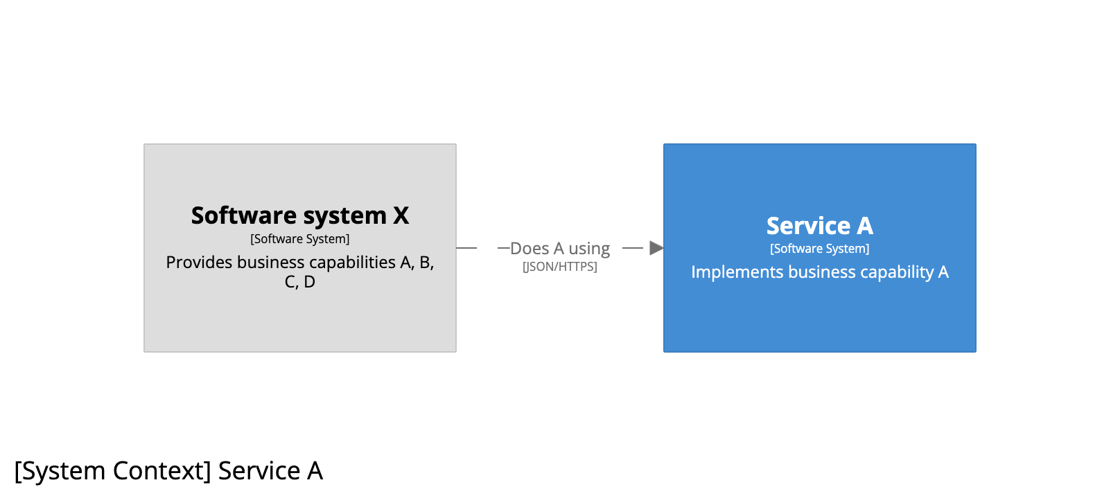
And from the perspective of team A, the system context diagram for service A looks like this:
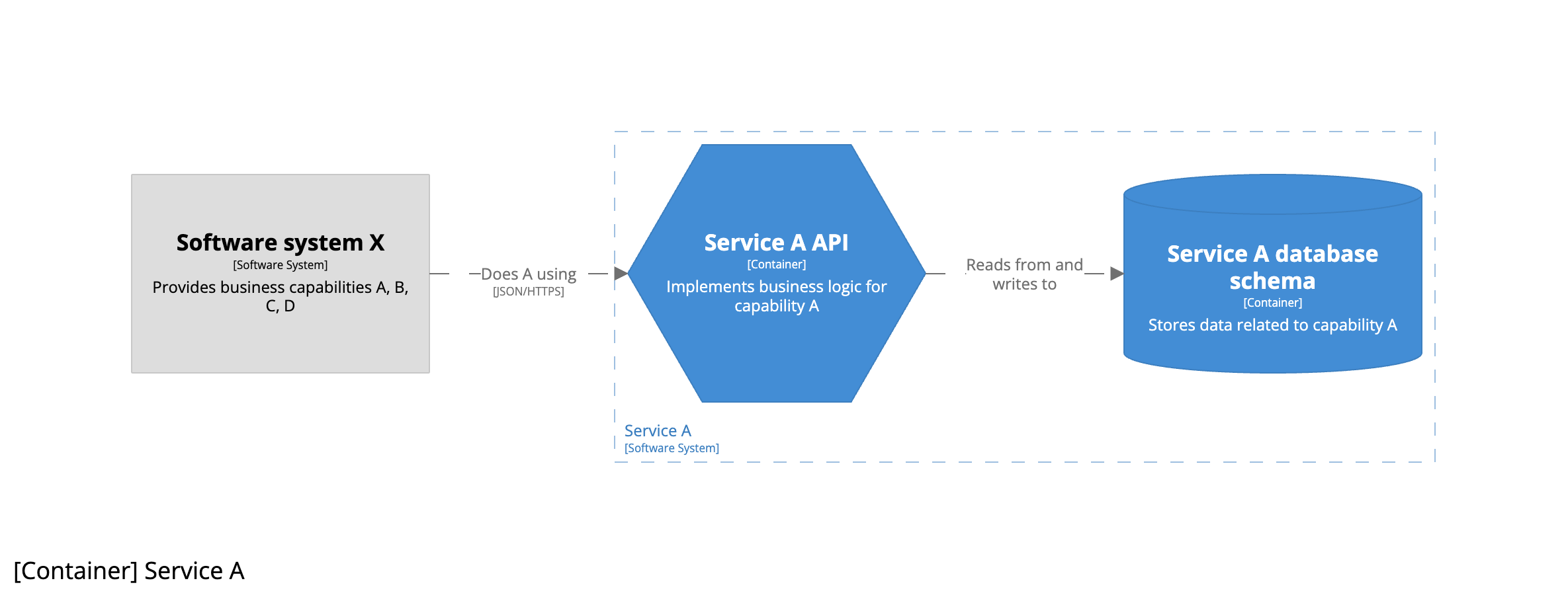
And the container diagram for service A looks like this:
Summary
The approach to take for diagramming a microservices architectural style depends upon the ownership of the individual services, and whether you see them as an implementation detail inside a single software system or as separate software systems that are (or could be) owned by separate teams.